The first part I’ll be making, will be the crankcase. Alongside the crankshaft, the crankcase will be essential on proofing the design of the built up crankshaft.
To better illustrate the steps in machining the parts, I’ll start with the CAD renderings of the finished parts. This will help to visualize the different setups.
The top half of the crankcase:


…and the bottom half:

I started with the inside of the two halves, by milling out the pockets that will make room for the connecting rods.


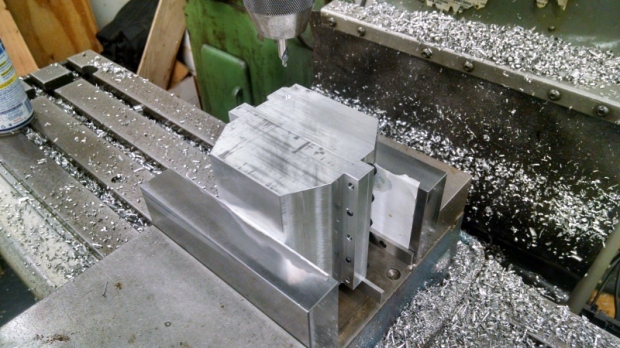
Next is the outside shape. First, I milled the flange where the two halves will be screwed together. Second operation was to mill the angled relief.


The same process was used for the top half of the case, except one side is different where it will house the cam shaft.

The two halves stacked on top of each other, to get the first impression of how this engine will look like.

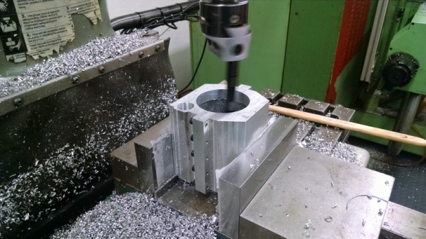
The next step is to bore out the case for the crank and cam shafts.
The two halves are screwed together and set up vertical in the vise.
Using a boring head, I started with the bore that will hold the camshaft.

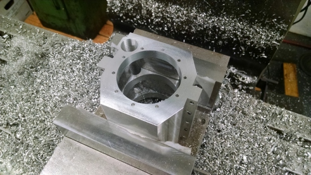
… and continued with the bore that will hold the crankshaft bearings.
At this stage the crankcase was faced over, to ensure the surface is perpendicular to the bore, and the hole pattern for the cover was drilled. The operation was repeated on the other side, machining the case to its final length.
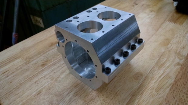
The last operation was to drill and bore the top to finish the case.

The finished crankcase (minus a few threads needing to be tapped  )
)

Thank you for visiting my shop.
If you have any questions about the engine or any of the other projects, please leave a comment below, or email me at yogisworkshop(at)yahoo.com
For other projects from the shop, please check out the projects page in the top menu.
Yogi

I’m following along. Nice presentation of the operations.
LikeLike
Thank you for the comment Brian!
LikeLike